by admin
Keyway Slot Dimensions
- Ansi Standard Keyway Dimensions
- See Full List On Armstrongmetalcrafts.com
- Parallel Key And Keyway Sizes And Tolerances Miki Pulley
Keyway Chart


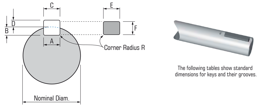
The following tables show standard dimensions for keys and their grooves.
Easily calculate the values required to cut keyseats and keyways. Find the depths to cut in keyway and keyseat. Also calculated are the overall measurements for shaft and bore, as well as the chord height. Just enter the size of the key and shaft, then click 'Calculate'. + Keyways will be furnished per ISO/R773 and Js9 width tolerance unless otherwise specified. (Dimensions comply with DIN 6885/1) † Requires use of chamfered keys. Surface Finish — Sides and bottom of keyways shall not exceed 250 micro inches.
Ansi Standard Keyway Dimensions
Metric – Rectangular
B.S.4235 : PART 1 : 1972

Key Size | ||||
Over | A | C | E | R |
12 | 3.970 4.000 | 3.985 4.015 | 4.030 3.970 | |
12 | 5 x 5 | 3.0 3.1 | 2.3 2.4 | 0.25 |
22 | 5.970 6.000 | 5.985 6.015 | 6.030 5.970 | |
22 | 8 x 7 | 4.0 4.2 | 3.3 3.5 | 7.000 6.910 |
30 | 10 x 8 | 5.0 5.2 | 3.3 3.5 | 8.000 7.910 |
38 | 12 x 8 | 5.0 5.2 | 3.3 3.5 | 8.000 7.910 |
44 | 14 x 9 | 5.5 5.7 | 3.8 4.0 | 9.000 8.910 |
50 | 16 x 10 | 6.0 6.2 | 4.3 4.5 | 10.000 9.910 |
58 | 18 x 11 | 7.0 7.2 | 4.4 4.6 | 11.000 10.890 |
65 | 20 x 12 | 7.5 7.7 | 4.9 5.1 | 12.000 11.890 |
75 | 22 x 14 | 9.0 9.2 | 5.4 5.6 | 14.000 13.890 |
85 | 25 x 14 | 9.0 9.2 | 5.4 5.6 | 14.000 13.890 |
95 | 28 x 16 | 10.0 10.2 | 6.4 6.6 | 16.000 15.890 |
110 | 32 x 18 | 11.0 11.2 | 7.4 7.6 | 18.000 17.890 |
130 | 36 x 20 | 12.0 12.3 | 8.4 8.7 | 20.000 19.870 |
150 | 40 x 22 | 13.0 13.3 | 9.4 9.7 | 22.000 21.870 |
170 | 45 x 25 | 15.0 15.3 | 10.4 10.7 | 25.000 24.870 |
200 | 50 x 28 | 17.0 17.3 | 11.4 11.7 | 28.000 27.870 |
Imperial – Rectangular
B.S.46 : PART 1 : 1958
Nominal Shaft Diam | Dimensions (Inches) | |||||||
To (incl.) | B | D | F | |||||
1 | 5/16 x 1/4 | 0.146 0.152 | 0.112 0.118 | 0.253 0.250 | ||||
1 1/4 | 3/8 x 1/4 | 0.150 0.156 | 0.108 0.114 | 0.253 0.250 | ||||
1 1/2 | 7/16 x 5/16 | 0.186 0.192 | 0.135 0.141 | 0.315 0.312 | ||||
1 3/4 | 1/2 x 5/16 | 0.190 0.196 | 0.131 0.137 | 0.315 0.312 | ||||
2 | 5/8 x 7/16 | 0.260 0.266 | 0.185 0.191 | 0.441 0.438 | ||||
2 1/2 | 3/4 x 1/2 | 0.299 0.305 | 0.209 0.215 | 0.503 0.500 | ||||
3 | 7/8 x 5/8 | 0.370 0.376 | 0.264 0.270 | 0.629 0.625 | ||||
3 1/2 | 1 x 3/4 | 0.441 0.447 | 0.318 0.324 | 0.754 0.750 | ||||
4 | 1 1/4 x 7/8 | 0.518 0.524 | 0.366 0.372 | 0.879 0.875 | ||||
5 | 1 1/2 x 1 | 0.599 0.605 | 0.412 0.418 | 1.006 1.000 | ||||
Imperial – Square
B.S.46 : PART 1 : 1958
Nominal Shaft Diam | Dimensions (Inches) | |||||||
To (incl.) | B | D | F | |||||
1/4 | 1/8 x 1/8 | 0.072 0.078 | 0.060 0.066 | 0.010 | ||||
3/4 | 0.187 0.188 | 0.188 0.189 | 0.190 0.188 | |||||
3/4 | 1/4 x 1/4 | 0.142 0.148 | 0.115 0.121 | 0.010 | ||||
1 1/4 | 0.311 0.312 | 0.312 0.313 | 0.314 0.312 | |||||
1 1/4 | 3/8 x 3/8 | 0.213 0.219 | 0.169 0.175 | 0.010 | ||||
1 3/4 | 0.437 0.438 | 0.438 0.439 | 0.440 0.438 | |||||
1 3/4 | 1/2 x 1/2 | 0.283 0.289 | 0.224 0.230 | 0.020 | ||||
2 1/2 | 0.624 0.625 | 0.625 0.626 | 0.627 0.625 | |||||
2 1/2 | 3/4 x 3/4 | 0.424 0.430 | 0.333 0.339 | 0.020 | ||||
3 1/2 | 0.874 0.875 | 0.875 0.876 | 0.877 0.875 | |||||
3 1/2 | 1 x 1 | 0.566 0.572 | 0.442 0.448 | 0.062 | ||||
5 | 1.248 1.250 | 1.250 1.252 | 1.253 1.250 | |||||
5 | 1 1/2 x 1 1/2 | 0.848 0.854 | 0.661 0.667 | 0.062 | ||||
DIN 6885/1 :- Definition
See Full List On Armstrongmetalcrafts.com
Drive Type Fastenings without Taper Action; Parallel Keys, Keyways, Deep Pattern

| d (from) mm | d (to) mm | bxh | t1 | t2 |
| 6 | 8 | 2x2 | 1.2 | 1 |
| 8 | 10 | 3x3 | 1.8 | 1.4 |
| 10 | 12 | 4x4 | 2.5 | 1.8 |
| 12 | 17 | 5x5 | 3 | 2.3 |
| 17 | 22 | 6x6 | 3.5 | 2.8 |
| 22 | 30 | 8x7 | 4 | 3.3 |
| 30 | 38 | 10x8 | 5 | 3.3 |
| 38 | 44 | 12x8 | 5 | 3.3 |
| 44 | 50 | 14x9 | 5.5 | 3.8 |
| 50 | 58 | 16x10 | 6 | 4.3 |
| 58 | 65 | 18x11 | 7 | 4.4 |
| 65 | 75 | 20x12 | 7.5 | 4.9 |
| 75 | 85 | 22x14 | 9 | 5.4 |
| 85 | 95 | 25x14 | 9 | 5.4 |
| 95 | 110 | 28x16 | 10 | 6.4 |
| 110 | 130 | 32x18 | 11 | 7.4 |
| 130 | 150 | 36x20 | 12 | 8.4 |
| 150 | 170 | 40x22 | 13 | 9.4 |
| 170 | 200 | 45x25 | 15 | 10.4 |
| 200 | 230 | 50x28 | 17 | 11.4 |
| 230 | 260 | 56x32 | 20 | 12.4 |
| 260 | 290 | 63x32 | 20 | 12.4 |
| 290 | 330 | 70x36 | 22 | 14.4 |
| 330 | 380 | 80x40 | 25 | 15.4 |
| 380 | 440 | 90x45 | 28 | 17.4 |
| 440 | 550 | 100x50 | 31 | 19.5 |
Parallel Key And Keyway Sizes And Tolerances Miki Pulley
Labels: DIN, Engineering Standards and Codes, feature